
Performance Level of Plasmasystem PB3/PS2000
Safety considerations according to EN ISO 13849
Processing units equipped with Relyon’s PS2000 and high power plasma jet can reliably reach performance level (PL) D. This makes it easy to design equipment, which is both state of the art and extremely safe. This article identifies the risks of high voltage powered plasma-processing units with clearly defined system boundaries and shows how these risks can be intercepted with appropriate technical measures.
Safety Systems
Safety systems are active or passive components that make production equipment safer for the operator and the environment.
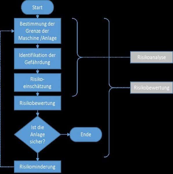
Machines and process equipment can be dangerous if operated inadequately, or faulty subsystems can lead to malfunction. In some cases, the damage can propagate and induce secondary failures if the equipment is not stopped immediately. However, even the best safety system relies on the operating personnel’s awareness of the potential hazards. Typically, production processes are controlled via software (PLC or computer) and embedded into an electrical and mechanical safety concept, which involves the following two steps: firstly, potential hazards have to be listed and their relative risk has to be assessed. Secondly, these critical situations have to be intercepted with a given reliability. Particularly electrical installations powered with dangerous voltages have to be shut down instantaneously, if necessary.
The following risk assessment is carried out using an inductive approach that analyzes different fault scenarios and how the system reacts to them. Statistical data is given regarding the probability of detecting faults and the likelihood that their effects can be reduced to an acceptable level. To this end, induced faults and their propagation through the safety system were studied.
System definition and boundaries
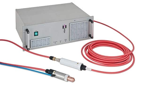
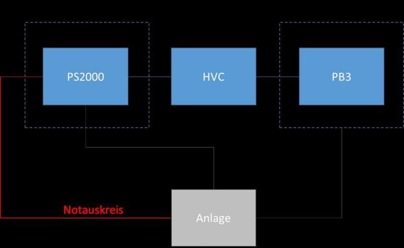
The power supply PS2000 is the central part of an atmospheric plasma system used to treat technical surfaces and materials. It is typically applied for surface activation prior to molding, coating casting, printing etc. The power supply is designed to be rack mounted (19inch standard) and to drive the Relyon PB3 atmospheric plasma generator. Therefore, the subsystem consisting of the power supply, the connecting cable and the plasma generator will be considered here.
The PS2000 is equipped with an emergency stop circuit that is included into this safety assessment.
Functional Reliability
In the following consideration, only the functional reliability and safety of the plasma sub-system are considered. It is assumed that said plasma system is embedded into a well-designed and functional environment, and that the safety means (light barriers etc.) are working correctly. It is also assumed that the plasma system has been integrated in compliance with the manual and operation instructions issued by Relyon Plasma. The overall function of the complete process equipment cannot be assessed here. Particularly, it is assumed that if an external failure occurs the emergency stop is triggered reliably.
Possible hazards (identification)
- Contact with unmounted PB3 plasma generator, enclosure opened
- Contact with plasma beam during process operation
- Damage of the high voltage cable
- Unplugging the HVC from the PB3 during operation
- Unplugging the HVC from the PS2000 during operation
All failures involving high potentials are considered as severe hazards with potentially lethal consequences, which is why the safety concept has to be 100% reliable.
Hazards 1 and 2 (contact with unmounted PB3 plasma generator with enclosure opened, contact with plasma beam during process operation) can occur in day-to-day operation (manual service, exchange of nozzle etc.) and would be critical if the high voltage were not switched off.
Both these hazards are reliably intercepted if the emergency circuit of the PS2000 is correctly embedded into the safety concept of the process equipment.
Hazard 3 (damage of the high voltage cable) will only occur in extremely few cases. Identical equipment has been working for a cumulated 105 hours or more and similar defects have only been observed in fewer than 10 instances. In most of these situations, the cable was damaged mechanically due to violent interaction. In all reported cases, the PS2000 switched off instantaneously triggered by a detection of a low HV status. If the equipment is restarted, the same failure will once again shut down the high voltage and trigger the emergency stop.
Cable damage was simulated practically by truncation in order to document the effect and to log the system reaction. Under unfavorable conditions, an electric arc may result, which is however instantly contained as the cable is made of flame retardant and self-extinguishing material.
Hazards 4 and 5 (unplugging the high voltage cable during operation, respectively from the PB3 for hazard 4 and from the PS2000 for hazard 5) will only occur if during service activities the HVC is disconnected without interrupting the process, or if the process is started while the cables are still disconnected. The frequency is estimated to be one per annum for each of these operating errors. All connectors are designed and certified to be protected against direct contact with the high voltage side (male/female concept) and insulated against voltage surge. Additionally, the power supply will detect the loadless situation and switch off after about one second. Communication will still be running.
In summary, hazards 1 and 2 have to be intercepted via emergency stop actions within the process equipment safety concept, while hazards 3-5 are detected by the PB3 or PS2000 internally and will also trigger the emergency stop.
Performance level of the internal emergency circuit
The only critical interface carrying hazardous voltages is the high voltage line. The high voltage is generated using an active switching unit and transformer (switching power supply). If the PWM signal of the switching unit is interrupted, the potential disappears. No direct galvanic connection to the grid power is present at this interface. Hence, a shut-down of the high voltage may be triggered using two independent channels: by disconnecting the PFC voltage from the power stage using the implemented relay, or by stopping the PWM of the final stage. The communication (CAN bus) runs on a separate micro-controller and is affected by either.
Emergency shutdown (located at the back of the PS2000 device)
The PS2000 power supply is delivered with a connector which is plugged into an external emergency stop circuit (normally open function).
If triggered, this emergency circuit disconnects the high power stage and PFC from the grid by opening a relay and stops the PWM signal for the generation of switched high voltage.
The internal relay has an MTTF of 3*104 cycles. If the relay locks, the power stage still gets the power from the PFC. In this case, additional safety reserve is provided through stopping the heartbeat needed for the active high voltage generation. To verify the reliability of this process, the emergency was induced 104 times using two PS2000 devices with clamped disconnecting relays (induced damage). There was not a single case in the loop test of this hardware in which a dangerous voltage was found even though the relay was clamped on intentionally.
Given the logged data of the tests, the failure probability can be calculated as follows:
Prel < 1/24*1/30.000 = 1.38 x 10⁻⁶
Psoft < 10-4
Pemergency shutdown < 1.38e-6*10-4 = 1.38*10-10
Risk assessment of HV cable damage
Damage of the HV cable was simulated practically using different mechanical means (cutting, squeezing, crushing and burning).
During the 200 documented induced failures, the power supply (PS2000) always detected an error and triggered the emergency stop. Communication and failure reporting continued to be active via the CAN interface. From these experimental findings, the failure probability can be calculated as follows:
Pcable damage < 10/300/4000 = 8.33*10-6
Precognition failure < 1/200 = 5*10-3
For 200 induced cable damages, the upper limit for critical failures involving high voltage is calculated to be:
PHV < 4.16*10-8
Risk assessment of incorrect disconnection of the high voltage cable (failure 4 and 5)
Assuming that once a year the connection is opened under load, the probability of this failure can be calculated as follows:
Pdisconnection < 2/365*24 = 2.28*10-4
Precognition failure<1/10.000
PHVC<2.3*10-8
This risk assessment was carried out by confirming the shut-down of the HV at missing load 10,000 times.
Integrated risk summary
Summing up the different hazard risks weighted with the probability to avoid the hazard by related safety means yield the conclusion that the probability of a dangerous failure is <10-7 per hour.
As shown in the table below, a plasma system assembled of the described components can reach performance level D.
| Performance Level (PL) according to EN ISO 13849-1 | Probability of fatal error per hour | Safety integrity level (SIL) according to IEC 61508 |
| A | 10-4 – 10-5 | – |
| B | 10-5 – 3 10–6 | 1 |
| C | 3 10-6 – 10-7 | 1 |
| D | 10-7 – 10-8 | 2 |
| E | 10-7 – 10-8 | 3 |
Diagram 4 overview of PL classification
Summary
Using a risk assessment methodology applied on empirical data and failure scenarios, we have been able to prove that our plasma systems reach a high performance level and safety. Using the modern approach of redundant safety circuits critical hazard can be avoided efficiently.