White paper: Lifetime of the Standard Module
Plasma expert Dr. Dariusz Korzec and his team have extensively tested the lifetime of the Module Standard. This module can be used for the entire piezobrush® product range from relyon plasma, including the piezobrush® PZ3 handheld device and the compact plasma integration piezobrush® PZ3-i for production lines.
Summary of the endurance test
The subject of the study is the investigation of the long-term durability of Standard Modules. For the endurance test, 10 piezobrush® PZ3 devices were used in combination with the Standard Modules, which are equipped with a polybutylene terephthalate (PBT) plasma liner. The modules were in operation for 37 weeks – more than 6000 hours. They were paused only briefly in between to measure the electrical parameters and the activation area.
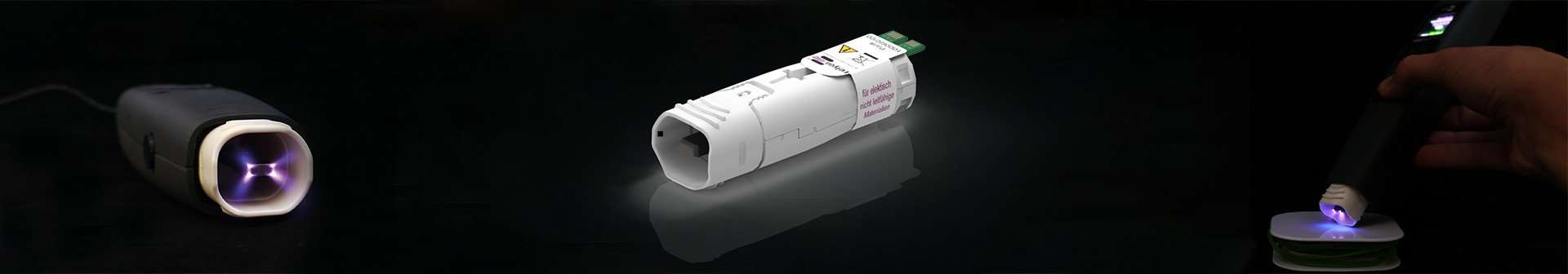
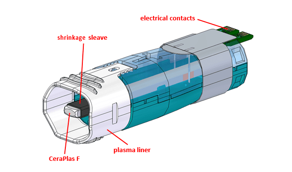
The core of the Standard Module is the CeraPlas® F. The high voltage generated with it leads to the ignition of the Piezoelectric Direct Discharge (PDD). A gas flow was maintained around the CeraPlas F. In the case of the piezobrush® PZ3, ambient air was used for this, in the case of the piezobrush® PZ3-i either compressed dry air (CDA) or nitrogen.
In the test performed, a continuous test cabinet was equipped with 10 holders for Standard Modules operated without substrates. All piezobrush® PZ3 handheld devices were set to continuous operation.
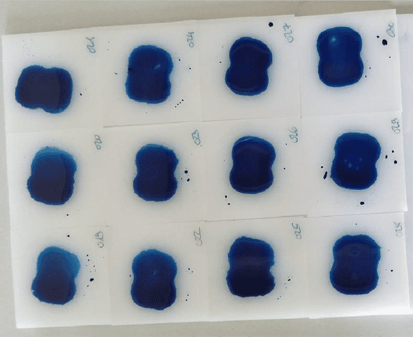
Every two weeks, all tested modules were removed from the piezobrush® PZ3, inspected for damage or wear, measured electrically, and also the activation area was measured. The latter is done with the help of the activation image recording system (AIR). In the first step of this procedure, the substrates made of high-density polyethylene (HDPE) were statically activated with the same piezobrush® PZ3. Three substrates were then treated with each standard module. The distance between the nozzle edge and the substrate was 4.0 mm and the treatment time was 10 seconds.
After treatment, each substrate was positioned on the base of the AIR system and the AIR procedure was performed. The activation area was visualized with two drops of a 58 mN/m test ink applied to the plasma-treated surface with a small brush immediately after the plasma treatment. The observed behavior of the test ink means that the substrate had a higher surface energy than 58 mN/m. Otherwise, the test ink would not wet the HDPE substrate.
The most important evaluation parameter is the average of the mean values of the activation areas determined per module. In the example, it was 612.7 mm2. Another important global parameter is the standard deviation of the module-related mean values of the activation area. In the present example, it was 13.19 mm2, which corresponds to 2.2%. This parameter provides information about the reproducibility of the activation performance from piece to piece. This parameter should be particularly low in the present case.
Several factors influence the accuracy of the activation area determination:
- Aging of the test ink: A test ink that has been stored in air for a long time changes its properties and shows a significantly smaller activation area than a fresh test ink.
- Different HDPE properties: The properties of HDPE substrates vary from supplier to supplier and batch to batch.
- The influence of surface pretreatment: Various preparation procedures for the HDPE surface prior to plasma treatment are known.
The following measures have been taken to minimize the undesirable influences:
- To avoid the influence of aging of the test ink on the activation surface results, the test ink bottle was always stored sealed before it was used to apply the ink. In addition, for each series of measurements, a fresh test ink bottle was opened and labeled with an opening date.
- Only the “natural” HDPE from a single supplier was used for the study. The substrates of some batches had different surface properties on both sides, as one side was sometimes glossy and sometimes matte. However, the difference in activation area depending on the side of the substrate was not statistically significant. The substrates used were also not completely flat, but had a concave and a convex side. Therefore, for equal test conditions, each substrate was positioned with the convex side up.
- To avoid the influence of solvents and water on the results, no wet treatment of the substrates was performed. To remove dust particles and sawdust residues, the surfaces were wiped dry with paper towels.
The activation area varied with the duration of the endurance test. During the first 2000 hours, the activation area decreased slightly. From about 2000 hours onwards, an increase was observed. The maximum value, reached after 6000 hours, was 26% higher than the minimum value.
The test system, linked to a database, was used to measure and store the electrical parameters of the CeraPlas® F of the modules tested. Each time the activation range was determined with the AIR system, the module was plugged into the electronic docking station and the excitation frequency, input voltage and current were automatically measured. Impedance was selected to monitor the change in module characteristics over time. There was a clear trend: a slight increase during the first 2000 hours and a monotonic decrease of 19% overall between 2000 and 6000 hours of operation. This trend was opposite to that of the activation area, which first slightly decreased and then increased.
Conclusion on the lifetime of Standard Module
All modules passed the 6000 hours of the endurance test without significant performance degradation. During the test, the activation area varied between 500 and 600 mm2. The input impedance of the CeraPlas® F decreased over 2000 h with the endurance test time. After 6000 h, it was 19% below the maximum value of 5800 mΩ. Both the increase in activation area and the decrease in input impedance of the CeraPlas® F can be explained by the loosening of the shrink sleeve, which resulted in less mechanical damping of the CeraPlas® F vibrations.
Click here for the full white paper.